
USE OF “HAARP” AS AN EARTHQUAKE WEAPON- PROTECTED BY U.S. PATENT!?

The article originally prepared by> SERBian FBReporter, 28.08.2012
“Former Governor of Minnesota and noted conspiracy theorist Jesse Ventura questioned whether the government is using the site to manipulate the weather or to bombard people with mind-controlling radio waves. An Air Force spokeswoman said Ventura made an official request to visit the research station but was rejected-“he and his crew showed up at HAARP anyway and were denied access”.[20]“(Juneau Empire-17 Oct.2011)
———————————————-
Link between HAARP earth-penetrating tomography technology and earthquakes.

The High-frequency Active Auroral Research Program (HAARP) is a congressionally initiated program jointly managed by the U.S. Air Force and U.S. Navy. The United States Congressional records show that HAARP is funded by the US government. The U.S. Senate set aside $15 million dollars in 1996 (Clinton administration) to develop the ability to penetrate the earth with signals bounced off of the ionosphere. This earth-penetrating-tomography has since been developed and used by the US government to look inside the planet to a depth of many kilometers in order to locate underground munitions, minerals and tunnels. The problem is that the frequencies used by HAARP for earth-penetrating tomography is also within the frequency range most cited for disruption of earth’s own electromagnetic field.
HAARP patents states that HAARP can beam radio energy into the Auroral electrojet, the curved, charged-particle stream formed at high latitudes where the solar wind interacts with Earth’s magnetic field. The radio energy then disperses over large areas through ductlike regions of the ionosphere, forming a virtual antenna that can be thousands of miles in length.
Such an ELF antenna can emit waves penetrating as deeply as several kilometers into the ground, depending on the geological makeup and subsurface water conditions in a targeted area. HAARP uses ground-penetrating radar (GPR) to beam pulses of polarized high-frequency radio waves into the ionosphere. These pulses can be finely tuned and adjusted so that the bounced ground penetrating beam can target a very specific area and for a specific length of time. Beaming a very large energy beam into the ground for an extended period can cause an earthquake. After all, an earthquake is the result of a sudden release of energy in the Earth’s crust that creates seismic wave resonances. The same array of antennas that are used by HAARP for ground penetrating tomography can also be used to penetrate deep into the ground and cause an earthquake anywhere around the World.
Geophysical events like earthquakes and volcanic eruptions – the kinds of things that may already be on the edge of discharge – can, with the right resonant energies added into the system, cause them to overload and actually fracture. Former U.S. Secretary of Defense William S. Cohen actually made the statement regarding weapons of mass destruction and the idea of generating earthquakes artificially. In a April 28, 1997 DoD News Briefing at the Conference on Terrorism, Weapons of Mass Destruction, and U.S. Strategy at the Georgia Center, Mahler Auditorium, University of Georgia, Athens, Ga. Cohen stated: “Others are engaging even in an eco- type of terrorism whereby they can alter the climate, set off earthquakes, volcanoes remotely through the use of electromagnetic waves.”
United States Patent 5041834 – Artificial ionospheric mirror composed of a plasma layer which can be tilted.
METHOD AND APPARATUS FOR ALTERING A REGION IN THE EARTH’S ATMOSPHERE, IONOSPHERE, AND/OR MAGNETOSPHERE
——————————————————
“HAARP PROTECTED”: United States Patent 5041834– Inventor Koert Peter, Washington, DC
| 4817495 | Defense system for discriminating between objects in space | April, 1989 | Drobot | 89/11.1 |
| 4712155 | Method and apparatus for creating an artificial electron cyclotron heating region of plasma | December, 1987 | Eastlund et al. | 361/231 |
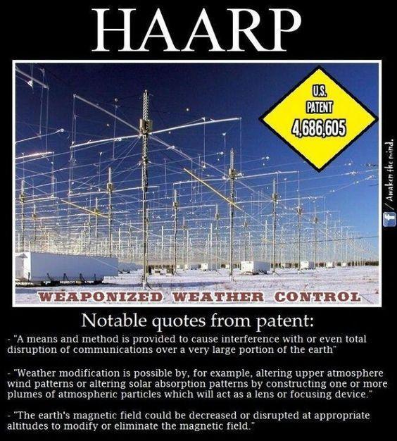
| 4686605 | Method and apparatus for altering a region in the earth’s atmosphere, ionosphere, and/or magnetosphere | August, 1987 | Eastlund | 361/231 |
| 4253190 | Communications system using a mirror kept in outer space by electromagnetic radiation pressure | February, 1981 | Csonka | 455/12 |
| 3445844 | TRAPPED ELECTROMAGNETIC RADIATION COMMUNICATIONS SYSTEM | May, 1969 | Grossi et al. | 342/367 |
What is claimed is:1. A method for generating an AIM, comprising the steps of:(a) creating avalanche ionization in the atmosphere using a heater antenna;(b) refocusing said heater antenna to alter the altitude of said avalanche ionization by frequency shifting said heater antenna; and
(c) scanning said heater antenna to paint an avalanche ionization layer.
2. A method for generating an AIM as claimed in claim 1 wherein said heater antenna is focused in the near field.
3. An apparatus for generating an AIM comprising:(a) a phased array heater antenna which is focused at an altitude to cause an avalanche ionization area to be created in the atmosphere;
(b) means for controlling frequency of individual radiators of said phased array heater antenna to refocus said altitude of said avalanche ionization area; and
(c) means for controlling phase of the individual radiators to scan said phased array heater antenna.
4. An apparatus for generating an AIM as claimed in claim 3 wherein said phased array heater antenna is focused to cause said avalanche ionization area to be substantially a line.
5. An apparatus for generating an AIM as claimed in claim 4 wherein said means for controlling phase moves said line substantially at a constant altitude and said means for controlling frequency moves said line to different altitudes.
6. An apparatus for generating an AIM as claimed in claim 4 wherein said phased array heater antenna is a rectangular array and said line is formed parallel to a long dimension of said rectangular array.
7. An apparatus for generating an AIM as claimed in claim 3 wherein said phased array heater antenna is focused to cause said avalanche ionization area to be substantially a point.
8. An apparatus for generating an AIM as claimed in claim 7 wherein said means for controlling the phase moves said point substantially at the same altitude and said means for controlling frequency moves said point to different altitudes.
9. An apparatus for generating an AIM as claimed in claim 3 wherein said phased array heater antenna is focused in the near field.
10. A method of generating an AIM comprising the steps of:(a) focusing a phased array heater antenna at an altitude to cause an avalanche ionization area to be created in the atmosphere;
(b) controlling the frequency of individual radiators of said phased array heater antenna to refocus said altitude of said avalanche ionization area;
(c) controlling phase of the individual radiators to scan said phased array heater antenna.
11. A method of generating an AIM as claimed in claim 10 wherein said step of focusing causes said avalanche ionization are to be substantially a line.
12. A method of generating an AIM as claimed in claim 11 wherein said step of controlling phase moves said line substantially at a constant altitude and said step of controlling frequency moves said line to different altitudes.
13. A method of generating an AIM as claimed in claim 11 wherein said phased array heater antenna is a rectangular array and said line is formed parallel to a long dimension of said rectangular array.
14. A method of generating an AIM as claimed in claim 10 wherein said step of focusing causes said avalanche ionization area to be substantially a point.
15. A method of generating an AIM as claimed in claim 14 wherein said step of controlling phase moves said point substantially at the same altitude and said step of controlling frequency moves said point to different altitudes.
16. A method of generating an AIM as claimed in claim 10 wherein said step of focusing is performed in the near field.
BACKGROUND OF THE INVENTION
1. Field of the Invention
This invention relates to generation of a Artificial Ionospheric Mirror (AIM), or a plasma layer in the atmosphere. The AIM is used like the ionosphere to reflect RF energy over great distances.
2. Description of the Related Art
In the past, the technique of using the ionosphere as a mirror to reflect radio waves, or RF energy, has given Ham Radio operators the ability to send transmissions over long distances. This technique has also provided radar systems the ability to look “over the horizon.” Variations and fluctuations in the ionosphere, however, can render the effectiveness of such communications uncertain. Thus, the desirability of creating controllable plasma layers in the atmosphere for communications purposes has been recognized. See, for example, U.S. Pat. No. 4,686,605 issued to Eastlund and U.S. Pat. No. 4,712,155 issued to Eastlund et al.
Previous experiments directed toward creating plasma layers for communications have suffered from the inability to control the inclination of the plasma layer so that signals could be transmitted and received from various ranges. In other words, while one could create a plasma layer in the atmosphere at a lower altitude than the ionosphere, point to point communications would be limited in range based on the reflection angles of the transmitted and reflected signals.
SUMMARY AND OBJECTS OF THE INVENTION
In view of the limitations of the related art it is an object of this invention to generate a plasma layer that could be angled or tilted with respect to the horizon in order to affect signal transmission range.
The present invention provides a system and method for generating a plasma layer at controlled altitudes and inclinations that acts as an artificial ionospheric mirror (AIM) to reflect RF signals. The AIM increases the range and predictability with which RF energy may be reflected off the AIM for communications purposes. More specifically, a tiltable AIM is created by a heater antenna controlled in phase and frequency. The heater antenna phase shift scans a beam to paint a plasma layer. The heater antenna continually refocuses at a higher altitudes by frequency shifting to tilt the plasma layer.
BRIEF DESCRIPTION OF THE DRAWINGS
Further details of the present invention are explained with the help of the attached drawings in which:
FIG. 1 shows creation of an AIM by a heater antenna and use of the AIM for tracking aircraft and reflecting radio waves.
FIG. 2 shows a typical heater array.
FIG. 3 shows the spacial relationship for a heater array used in defining heater array focusing.
FIG. 4 is a graph showing that power is at its upper bound at the antenna focal point.
FIG. 5 shows generation of plasma by a heater array.
FIG. 6 illustrates generation of a plasma layer by scanning a heater antenna.
FIG. 7 illustrates generation of a tilted plasma layer by scanning and refocusing a heater antenna.
FIG. 8 shows generation of a plasma layer using a heater antenna to scan with a line rather than a point.
FIG. 9 shows the phase corrections to move the antenna focal point from 60 Km to 61 Km.
FIG. 10 shows the frequency corrections to move the antenna focal point from 60 Km to 61 Km.
FIG. 11 is a plot of altitude v. distance location of plasma without frequency chirping.
FIG. 12 is a plot of altitude v. distance location of plasma with frequency chirping.
FIG. 13 shows the power density change after refocusing using frequency chirping .
FIG. 14 graphs the free electron density v. altitude for an unfocused array.
FIG. 15 shows an antenna power pattern without grating lobes.
FIG. 16 shows an antenna power pattern with grating lobes.
DETAILED DESCRIPTION OF THE PREFERRED EMBODIMENTS
FIG. 1 illustrates the creation and use of An Artificial Ionospheric Mirror (AIM) for tracking aircraft and reflecting radio waves. A heater antenna 1 radiates power causing avalanche ionization or breakdown releasing free electrons in the atmosphere to generate the AIM 2. The heater antenna 1 is an array which can be used to focus energy at varying altitudes and elevations to tilt the AIM 2 using phase and frequency control. The AIM 2 simulates the ionosphere 3 which is also used to detect “over the horizon targets” 5. In addition, the AIM 2 can reflect radio signals transmitted from a transmitter 6 to a receiver 7 over long distances.
A typical heater antenna is shown in FIG. 2. It consists of an array of multiple active radiating elements 10 having their individual phase and frequency controlled from a control module 12. The radiating element 10 is used here to represent all possible antennas, including, but not limited to, dipoles, slots, small or large horns, log-periodic antennas, large parabolic reflectors, etc.
FIG. 3 shows the spatial relationship for a focused heater array. To have the electric fields from all of the array elements focus, or arrive in phase at a distance Ro in the near field of the array, it is necessary to correct the phase of each element to compensate for the phase delay difference from the center element due to the additional phase path Wij. If Ro is much larger than the maximum Dij in FIG. 3, then the phase delay can be approximated in wavelength to be: Wij =(Dij)2 /(4*R*g) (1)
where g is the wavelength of the heater frequency. Equation 1 is referred to as the quadratic phase error. If this error is less than g/8 when the element (i,j) is on the outer edge of the array, then the distance Ro is said to be in the far field of the array.
In order to focus the array at Ro, it is necessary to have several wavelengths of phase error from the outer elements of the array. That is, the term “focus” is used in this context to mean that the electric field from the array is concentrated in a desired spatial region.
FIG. 4 shows the degree of focusing that can be accomplished. This is a vertical pattern of an array whose elements have been phase shifted to focus at 60 Km. The array has 400 elements with a total width and length of 2000 g. The peak of the pattern is determined by the 1/Ro2dependence.
The AIM ionization layer is created by using this focused power to ionize an area in the atmosphere, as shown in FIG. 5. The microwave breakdown of air occurs where free electrons gain enough energy from an electric field to generate additional free electrons until no more can be generated, thereby resulting in avalanche ionization, or breakdown. This causes the generation of a plasma layer 21. For example, a pulse of power from the heater begins to propagate in the z direction shown in FIG. 5. As the field propagates, more free electrons are generated. A breakdown point descends vertically from the focal point of the propagating field giving thickness to the ionized layer, or plasma layer, until all ionization stabilizes. This “clamping” creates a thin vertical plasma layer.
Simulation results show that when an array 20 is focused at a point 22, electric field power peaks at the focal point. Simulation results shows that given a focused microwave source avalanche ionization, or breakdown will occur at a power level 3-10 dB below the focal point power level.
To create an AIM, the heater array is focused at a desired altitude to maximize power at a point and thereby generate plasma. The heater antenna then “scans” the phase of each array element to move the focal point.
FIG. 6 illustrates creation of a noninclined AIM layer. The heater array 30 is first focused at point 31. The heater array scans horizontally by phase shifting to a point 32 creating an avalanche ionization line 33. Next, the heater array scans from a point 34 to a point 35 creating another avalanche ionization line 36. The heater array continues this process to create an ionization plane or AIM layer.
In order to form an inclined AIM cloud, each new ionization line must occur at a slightly higher altitude. By altering the phase or frequency of the array elements, the focal point can be moved up in altitude, as described below.
FIG. 7 illustrates creation of an inclined AIM. The heater array 40 is first focused at point 41. The heater array scans along the x direction to point 42 to generate avalanche ionization along line 43. Next, as in creation of a non-inclined AIM, the heater array scans along the x and y directions directly below point 44. The heater array 40 alters either phase or frequency to refocus to a higher altitude in the z direction to the point 44. The heater array then scans along the x axis to point 45 to create the avalanche ionization line 46. The heater array continues this process to create a tilted ionization plane or tilted AIM layer.
FIG. 8 shows that the preferred method of generating a plasma layer uses a heater antenna to scan with a line rather than a point. Scanning using a line is preferred since an AIM can be created in the atmosphere in less time. To create lines of ionization rather than points, a rectangular array 50 is used. In the array 50, radiating elements are focused only along the plane of the long dimension of the rectangular array, creating a line of ionization 53. The array is then scanned along the x-y axis and in altitude along the z axis to create another ionization line 55. More ionization lines are similarly generated to form a tilted AIM layer.
In order to create a tilted AIM it is necessary to refocus the heater array at successively higher altitudes. Moving the focal point by changing the phase of each element of the heater in a very precise manner is not practical. Moving the focal point away from the initial location requires changing the phase on each element. The phase change required is near the rms tolerance level, typically 1 degree. FIG. 9 shows the required phase corrections to move the focal point from 60 Km to 61 km. Elements 5, 10, 15, and 20 have distances 5d, 10d, 15d, and 20d, respectively from the center of the antenna, where d=25 meters It is clear from FIG. 9 that it is impractical to alter numerous antenna element phases to move the focal point to create tilted patches for AIM applications. 2000 elements may be required here to generate enough power to ionize the atmosphere.
The second method of refocusing is accomplished by first setting the phases of all elements for the initial focal point and then moving the focal point by changing the frequency rather than the phase. This frequency chirping method is less precise, but easier for hardware implementation because precise phases for 2000 elements need not be changed. FIG. 9 shows the required phase corrections to move the focal point from 60 Km to 61 Km. FIG. 10 shows that the focal point can be moved 100 meters by increasing the frequency approximately 1 Mhz. The resulting focal point power levels are not completely optimized, but simulation shows that there is less than a 0.1 db difference between the frequency shifted peaks and those obtained by phasing.
Tilting the AIM using frequency chirping is practical to achieve in a real system. FIG. 11 shows the plasma layer location with no frequency chirping. FIG. 12 shows the plasma location of the same heater creating a tilted AIM by increasing frequency from 550 MHz to 559.375 MHz while scanning horizontally. The result is a smooth patch with a 45 degree inclination.
While it is true that frequency chirping does not achieve the same power as phase focusing at the higher altitude, the difference for small frequency chirps is negligible. FIG. 13 shows actual power density data generated by a 300 MHz heater focused at 70 km with the frequency chirped to 308 MHz.
In the far field region, power meets its upper bound without focusing. For a far field or unfocused array, there is no way to raise the ionization altitude or create a tilted AIM. Ionization takes place at a point where there is enough power to initiate breakdown and where there is low enough neutral density (i.e. pressure). This usually occurs between 40 and 50 km altitude as shown in FIG. 14. Consequently, a near field focused antenna is required to create a controlled AIM.
The focused pattern is a picture of constructive and destructive interference of the fields from the elements of the array. Other interference positions, or grating lobes, outside the focal point occur when some of the array elements add up in phase. The power of grating lobes can be kept below that of the main lobe, or focal point, by having a large number of elements in the array and spreading them out over the array aperture. This is called thinning the array. For square arrays having 400 elements or more grating lobes can be kept down by 20 db or more from the focal point.
The degree of focusing depends on the ratio of focal range to aperture size. The half power width from peak “V” can be approximated as: V=2*g*(Ro /L)2 (2)
where L is the length of the array which is assumed square for equation 2. The power gradient at the half power point “grad(P)” can be approximated as: grad(P)=10/V(db/meter) (3)
For an AIM it is desirable that the power gradient be high because this directly determines the gradient of the electron density of the generated ionized cloud. The electron density must be high to avoid RF losses caused by absorption. Hence V be small, preferably less than 2 Km. A heater frequency of 300 MHz and a focal distance of 70 Km would project an aperture size greater than 2 Km. Note in equation 2 that array size scales with the square root of frequency.
Since a near field antenna is required, the near field of the heater antenna may be required to extend to reach distant points. This is accomplished by increasing the array size. It may not be economically feasible to fill this entire aperture with elements, hence a thinned array is utilized.
If a thinned array had its elements uniformly distributed, there would be many grating lobes in the radiation pattern of the array. These grating lobes can be eliminated by randomly spacing elements. However, random spacing puts power from the grating lobes into the average side lobe level. If no new elements are introduced when the aperture is increased, then the peak power of the main lobe remains constant and the main lobe receives less of the total power as its beamwidth decreases. In order to preserve the efficiency of the heater array, grating lobes must be utilized in creating the AIM cloud or the array can not be heavily thinned. FIG. 15 shows an array with uniform spacing having grating lobes. FIG. 16 shows an array with randomized spacing which eliminates the grating lobes.
Although the invention has been described above with particular reference to certain preferred embodiments thereof, it will be understood that modifications and variations are possible within the spirit and scope of the appended claims.
——————————————————————————–
THE PUBLISHED FACTS ABOUT “High Frequency Active Auroral Research Program”

|
|
| Established | 1993 |
|---|---|
| Research type | Unclassified |
| Field of research | Ionosphere |
| Director | John Heckscher |
| Location | Gakona, Alaska |
| Affiliations | University of Alaska |
| Operating agency | Office of Naval Research Air Force Research Laboratory |
| Website | www.haarp.alaska.edu |
The High Frequency Active Auroral Research Program (HAARP) is an ionospheric research program jointly funded by the U.S. Air Force, the U.S. Navy, the University of Alaska, and the Defense Advanced Research Projects Agency (DARPA).[1]
Built by BAE Advanced Technologies (BAEAT), its purpose is to analyze the ionosphere and investigate the potential for developing ionospheric enhancement technology for radio communications and surveillance.[2] The HAARP program operates a major sub-arctic facility, named the HAARP Research Station, on an Air Force–owned site near Gakona, Alaska.
The most prominent instrument at the HAARP Station is the Ionospheric Research Instrument (IRI), a high-power radio frequency transmitter facility operating in the high frequency (HF) band. The IRI is used to temporarily excite a limited area of the ionosphere. Other instruments, such as a VHF and a UHF radar, a fluxgate magnetometer, a digisonde, and an induction magnetometer, are used to study the physical processes that occur in the excited region.
Work on the HAARP Station began in 1993. The current working IRI was completed in 2007, and its prime contractor was BAE Systems Advanced Technologies.[1] As of 2008, HAARP had incurred around $250 million in tax-funded construction and operating costs.
HAARP has been blamed by conspiracy theorists for a range of events, including numerous natural disasters. Various scientists have commented that HAARP is an attractive target for conspiracy theorists because according to computer scientist David Naiditch, “its purpose seems deeply mysterious to the scientifically uninformed”.[3]
Contents[hide] |
[edit] Objectives

HAARP antenna array
The HAARP project directs a 3.6 MW signal, in the 2.8–10 MHz region of the HF (high-frequency) band, into the ionosphere. The signal may be pulsed or continuous. Then, effects of the transmission and any recovery period can be examined using associated instrumentation, including VHF and UHF radars, HF receivers, and optical cameras. According to the HAARP team, this will advance the study of basic natural processes that occur in the ionosphere under the natural but much stronger influence of solar interaction, and how the natural ionosphere affects radio signals.
This will enable scientists to develop methods to mitigate these effects to improve the reliability or performance of communication and navigation systems, which would have a wide range of uses, civilian and military, such as an increased accuracy of GPS navigation, and advances in underwater and underground research and applications. This may lead to improved methods for submarine communication, or an ability to remotely sense and map the mineral content of the terrestrial subsurface, and perhaps underground complexes, of regions or countries, among other things. The current facility lacks the range to reach these countries, but the research could be used to develop a mobile platform.[4]
The HAARP program began in 1990. The project is funded by the Office of Naval Research and jointly managed by the ONR and Air Force Research Laboratory, with the principal involvement of the University of Alaska. Many other universities and educational institutions of the United States have been involved in the development of the project and its instruments, namely the University of Alaska Fairbanks, Stanford University, Penn State University (ARL), Boston College, UCLA, Clemson University, Dartmouth College, Cornell University, Johns Hopkins University, University of Maryland, College Park, University of Massachusetts Amherst, MIT, Polytechnic Institute of New York University, and the University of Tulsa. The project’s specifications were developed by the universities, which are continuing to play a major role in the design of future research efforts.
According to HAARP’s management, the project strives for openness, and all activities are logged and publicly available. Scientists without security clearances, even foreign nationals, are routinely allowed on site. The HAARP facility regularly (once a year on most years according to the HAARP home page) hosts open houses, during which time any civilian may tour the entire facility. In addition, scientific results obtained with HAARP are routinely published in major research journals (such as Geophysical Research Letters, or Journal of Geophysical Research), written both by university scientists (American and foreign) or by U.S. Department of Defense research lab scientists. Each summer, the HAARP holds a summer school for visiting students, including foreign nationals, giving them an opportunity to do research with one of the world’s foremost research instruments.
[edit] Research
HAARP’s main goal is basic science research of the uppermost portion of the atmosphere, termed the ionosphere. Essentially a transition between the atmosphere and the magnetosphere, the ionosphere is where the atmosphere is thin enough that the sun’s X-rays and UV rays can reach it, but thick enough that there are still enough molecules present to absorb those rays. Consequently, the ionosphere consists of a rapid increase in density of free electrons, beginning at ~70 km, reaching a peak at ~300 km, and then falling off again as the atmosphere disappears entirely by ~1,000 km. Various aspects of HAARP can study all of the main layers of the ionosphere.
The profile of the ionosphere is highly variable, changing constantly on timescales of minutes, hours, days, seasons, and years. This profile becomes even more complex near Earth’s magnetic poles, where the nearly vertical alignment and intensity of earth’s magnetic field can cause physical effects like aurorae.
The ionosphere is traditionally very difficult to measure. Balloons cannot reach it because the air is too thin, but satellites cannot orbit there because the air is still too thick. Hence, most experiments on the ionosphere give only small pieces of information. HAARP approaches the study of the ionosphere by following in the footsteps of an ionospheric heater called EISCAT near Tromsø, Norway. There, scientists pioneered exploration of the ionosphere by perturbing it with radio waves in the 2–10 MHz range, and studying how the ionosphere reacts. HAARP performs the same functions but with more power and a more flexible and agile HF beam.
Some of the main scientific findings from HAARP include
- Generating very low frequency radio waves by modulated heating of the auroral electrojet, useful because generating VLF waves ordinarily requires gigantic antennas
- Generating weak luminous glow (measurable, but below that visible with a naked eye) from absorbing HAARP’s signal
- Generating extremely low frequency waves in the 0.1 Hz range. These are next to impossible to produce any other way, because the length of a transmit antenna is dictated by the wavelength of the signal it must emit.
- Generating whistler-mode VLF signals that enter the magnetosphere and propagate to the other hemisphere, interacting with Van Allen radiation belt particles along the way
- VLF remote sensing of the heated ionosphere
Research at the HAARP includes
- Ionospheric super heating[citation needed]
- Plasma line observations
- Stimulated electron emission observations
- Gyro frequency heating research
- Spread F observations (blurring of ionospheric echoes of radio waves due to irregularities in electron density in the F layer)
- High velocity trace runs
- Airglow observations
- Heating induced scintillation observations
- VLF and ELF generation observations[5]
- Radio observations of meteors
- Polar mesospheric summer echoes (PMSE) have been studied, probing the mesosphere using the IRI as a powerful radar, and with a 28 MHz radar, and two VHF radars at 49 MHz and 139 MHz. The presence of multiple radars spanning both HF and VHF bands allows scientists to make comparative measurements that may someday lead to an understanding of the processes that form these elusive phenomena.
- Research on extraterrestrial HF radar echos: the Lunar Echo experiment (2008).[6][7]
- Testing of Spread Spectrum Transmitters (2009)
- Meteor shower impacts on the ionosphere
- Response and recovery of the ionosphere from solar flares and geomagnetic storms
- The effect of ionospheric disturbances on GPS satellite signal quality
[edit] Instrumentation and operation
The main instrument at HAARP Station is the Ionospheric Research Instrument (IRI). This is a high power, high-frequency phased array radio transmitter with a set of 180 antennas, disposed in an array of 12×15 units that occupy a rectangle of about 33 acres (13 hectares). The IRI is used to temporarily energize a small portion of the ionosphere. The study of these disturbed volumes yields important information for understanding natural ionospheric processes.
During active ionospheric research, the signal generated by the transmitter system is delivered to the antenna array and transmitted in an upward direction. At an altitude between 70 km (43 mi) to 350 km (217 mi) (depending on operating frequency), the signal is partially absorbed in a small volume several tens of kilometers in diameter and a few meters thick over the IRI. The intensity of the HF signal in the ionosphere is less than 3 µW/cm², tens of thousands of times less than the Sun’s natural electromagnetic radiation reaching the earth and hundreds of times less than even the normal random variations in intensity of the Sun’s natural ultraviolet (UV) energy which creates the ionosphere. The small effects that are produced, however, can be observed with the sensitive scientific instruments installed at the HAARP Station, and these observations can provide information about the dynamics of plasmas and insight into the processes of solar-terrestrial interactions.[8]
Each antenna element consists of a crossed dipole that can be polarized for linear, ordinary mode (O-mode), or extraordinary mode (X-mode) transmission and reception.[9][10] Each part of the two section crossed dipoles are individually fed from a custom built transmitter, that has been specially designed with very low distortion. The Effective Radiated Power (ERP) of the IRI is limited by more than a factor of 10 at its lower operating frequencies. Much of this is due to higher antenna losses and a less efficient antenna pattern.
The IRI can transmit between 2.7 and 10 MHz, a frequency range that lies above the AM radio broadcast band and well below Citizens’ Band frequency allocations. The HAARP Station is licensed to transmit only in certain segments of this frequency range, however. When the IRI is transmitting, the bandwidth of the transmitted signal is 100 kHz or less. The IRI can transmit in continuous waves (CW) or in pulses as short as 10 microseconds (µs). CW transmission is generally used for ionospheric modification, while transmission in short pulses frequently repeated is used as a radar system. Researchers can run experiments that use both modes of transmission, first modifying the ionosphere for a predetermined amount of time, then measuring the decay of modification effects with pulsed transmissions.
There are other geophysical instruments for research at the Station. Some of them are:
- A fluxgate magnetometer built by the University of Alaska Fairbanks Geophysical Institute, available to chart variations in the Earth’s magnetic field. Rapid and sharp changes of it may indicate a geomagnetic storm.
- A digisonde that provides ionospheric profiles, allowing scientists to choose appropriate frequencies for IRI operation. The HAARP makes current and historic digisonde information available online.
- An induction magnetometer, provided by the University of Tokyo, that measures the changing geomagnetic field in the Ultra Low Frequency (ULF) range of 0–5 Hz.
[edit] Site
The project site (
 WikiMiniAtlas
62°23′30″N 145°09′03″W / 62.39167°N 145.15083°W / 62.39167; -145.15083) is north of Gakona, Alaska just west of Wrangell-Saint Elias National Park. An environmental impact statement led to permission for an array of up to 180 antennas to be erected.[11] The HAARP has been constructed at the previous site of an over-the-horizon radar (OTH) installation. A large structure, built to house the OTH now houses the HAARP control room, kitchen, and offices. Several other small structures house various instruments. The HAARP site has been constructed in three distinct phases:[12]
- The Developmental Prototype (DP) had 18 antenna elements, organized in three columns by six rows. It was fed with a total of 360 kilowatts (kW) combined transmitter output power. The DP transmitted just enough power for the most basic of ionospheric testing.
- The Filled Developmental Prototype (FDP) had 48 antenna units arrayed in six columns by eight rows, with 960 kW of transmitter power. It was fairly comparable to other ionospheric heating facilities. This was used for a number of successful scientific experiments and ionospheric exploration campaigns over the years.
- The Final IRI (FIRI) is the final build of the IRI. It has 180 antenna units, organized in 15 columns by 12 rows, yielding a theoretical maximum gain of 31 dB. A total of 3.6 MW of transmitter power will feed it, but the power is focused in the upward direction by the geometry of the large phased array of antennas which allow the antennas to work together in controlling the direction. As of March 2007[update], all the antennas were in place, the final phase was completed and the antenna array was undergoing testing aimed at fine-tuning its performance to comply with safety requirements required by regulatory agencies. The facility officially began full operations in its final 3.6 MW transmitter power completed status in the summer of 2007, yielding an effective radiated power (ERP) of 5.1 Gigawatts or 97.1 dBW at maximum output. However, the site typically operates at a fraction of that value due to the lower antenna gain exhibited at standard operational frequencies.[13]
[edit] Related facilities
In America, there are two related ionospheric heating facilities: the HIPAS, near Fairbanks, Alaska, which was dismantled in 2009, and (currently offline for reconstruction) one at the Arecibo Observatory[14] in Puerto Rico. The European Incoherent Scatter Scientific Association (EISCAT) operates an ionospheric heating facility, capable of transmitting over 1 GW effective radiated power (ERP), near Tromsø, Norway.[15] Russia has the Sura Ionospheric Heating Facility, in Vasilsursk near Nizhniy Novgorod, capable of transmitting 190 MW ERP.
[edit] Fringe speculations
HAARP is the subject of numerous conspiracy theories, with individuals ascribing various hidden motives and capabilities to the project. Journalist Sharon Weinberger called HAARP “the Moby Dick of conspiracy theories” and said the popularity of conspiracy theories often overshadows the benefits HAARP may provide to the scientific community.[16][17] Computer scientist David Naiditch has also referred to HAARP as “a magnet for conspiracy theorists”, saying the project has been blamed for triggering catastrophes such as floods, droughts, hurricanes, thunderstorms, and devastating earthquakes in Pakistan and the Philippines, major power outages, the downing of TWA Flight 800, Gulf War syndrome, and chronic fatigue syndrome.[3]
Specific allegations include the following:
- A Russian military journal wrote that ionospheric testing would “trigger a cascade of electrons that could flip earth’s magnetic poles”.[18]
- The European Parliament and the Alaska state legislature held hearings about HAARP, the former citing “environmental concerns”.[19]
- Author of the self-published Angels Don’t Play This HAARP, Nick Begich has told lecture audiences that HAARP could trigger earthquakes and turn the upper atmosphere into a giant lens so that “the sky would literally appear to burn”.[18]
- Former Governor of Minnesota and noted conspiracy theorist Jesse Ventura questioned whether the government is using the site to manipulate the weather or to bombard people with mind-controlling radio waves. An Air Force spokeswoman said Ventura made an official request to visit the research station but was rejected-“he and his crew showed up at HAARP anyway and were denied access”.[20]
[edit] In popular culture
HAARP has been dramatized in popular culture by Marvel Comics, author Tom Clancy (the novel Breaking Point in the Net Force series), and The X-Files.
A fictionalized HAARP was the setting for a stage in the X-Men Legends game.[21] HAARP was also featured in the animated series G.I. Joe: Resolute and in the first episode of Conspiracy Theory with Jesse Ventura.
The alternative rock band Muse named an album after this facility. HAARP’s various antennae also inspired the set design for the performance, which was recorded live at Wembley Stadium.
The progressive metal band The HAARP Machine named their band after the facility.
The film Metal Tornadoes depicts an attempt using HAARP-like technology to harvest energy from solar flares that turns into disaster when the stored energy leaks.
[edit] See also
- Ionospheric reflection
- EISCAT
- HIPAS
- Poker Flat Research Range
- SuperDARN
- Sura Ionospheric Heating Facility
- Weather Modification
[edit] References
- ^ a b “HAARP Fact Sheet”. HAARP. 15 June 2007. http://www.haarp.alaska.edu/haarp/factSheet.html. Retrieved 27 September 2009.
- ^ “Purpose and Objectives of the HAARP Program”. HAARP. http://www.haarp.alaska.edu/haarp/prpeis.html. Retrieved 27 September 2009.
- ^ a b Naiditch, David (Spring 2003). “Is baked Alaska half-baked?”. Skeptic Magazine. http://www.skeptic.com/eskeptic/10-03-03/#feature. Retrieved 25 January 2010.
- ^ Pentagon Scientists Target Iran’s Nuclear Mole Men
- ^ http://www-star.stanford.edu/~vlf/publications/2008-03.pdf
- ^ Reeve, W.D. (2008). “The Lunar Echo Experiment (Part 1)”. Radio User 3 (8): 56–58. ISSN 1748-8117.
- ^ Reeve, W.D. (2008). “The Lunar Echo Experiment (Part 2)”. Radio User 3 (9): 56–57. ISSN 1748-8117.
- ^ “Technical Information”. HAARP. 12 April 2007. http://www.haarp.alaska.edu/haarp/tech.html. Retrieved 27 September 2009.
- ^ “The HAARP Antenna Array”. HAARP. Archived from the original on 15 April 2007. http://web.archive.org/web/20070415111323/http://www.haarp.alaska.edu/haarp/ant3.html. Retrieved 27 September 2009.
- ^ “Details of the HAARP Antenna Design”. HAARP. Archived from the original on 13 May 2007. http://web.archive.org/web/20070513135131/http://www.haarp.alaska.edu/haarp/ant2.html. Retrieved 27 September 2009.
- ^ “The HAARP IRI As Described in the EIS”. 17 May 2007. http://www.haarp.alaska.edu/haarp/iriEis.html. Retrieved 27 September 2009.
- ^ “Phases of Completion of the IRI”. HAARP. Archived from the original on 1 May 2007. http://web.archive.org/web/20070501131817/http://www.haarp.alaska.edu/haarp/phases.html.
- ^ “HAARP IRI Performance Calculator”. 10 May 2010. http://www.haarp.alaska.edu/haarp/calciri.html. Retrieved 10 May 2010.
- ^ Link text
- ^ B. Isham, C. La Hoz, M. T. Rietveld, F. T. Djuth, T. Hagfors, and T. Grydeland (October 2000). “High Latitude HF-Induced Plasma Turbulence”. The First S-RAMP Conference. http://www.kurasc.kyoto-u.ac.jp/s-ramp/abstract/s19.txt. Retrieved 27 September 2009.
- ^ Weinberger, Sharon (23 April 2008). “Atmospheric physics: Heating up the heavens”. Nature. http://www.nature.com/news/2008/080423/full/452930a.html. Retrieved 21 January 2010.
- ^ Weinberger, Sharon (25 April 2008). “The Strange Life and Times of HAARP”. Wired Magazine. http://www.wired.com/dangerroom/2008/04/haarp/. Retrieved 21 January 2010.
- ^ a b Shachtman, Noah (20 July 2009). “Strange New Air Force Facility Energizes Ionosphere, Fans Conspiracy Flames”. Wired Magazine. http://www.wired.com/politics/security/magazine/17-08/mf_haarp?currentPage=2. Retrieved 17 April 2011.
- ^ “EU clashes with US over atmosphere tests”. physicsworld.com. IOP Publishing, 27 February 1998. http://physicsworld.com/cws/article/news/3302. Retrieved 17 April 2011.
- ^ Baenen, Jeff. “Ventura seeks out conspiracy theories at Alaska station”. Juneau Empire. http://juneauempire.com/stories/120309/sta_531557452.shtml. Retrieved 17 October 2011.
- ^ “X-Men Legends Plot”. Strategy Wiki. http://strategywiki.org/wiki/X-Men_Legends/Plot. Retrieved 24 August 2010.
[edit] Further reading
- Y. Zaitsev (11 May 2007). “From radio telescopes to electromagnetic weapons.”. Ria Novosti. http://en.rian.ru/analysis/20070511/65348455.html. Retrieved 27 September 2009.
- “Evidence for Precipitation of Energetic Particles by Ionospheric “Heating” Transmissions”. National Geophysical Data Center. 7 December 2004. http://www.ngdc.noaa.gov/stp/IONO/Dynasonde/SpEatHeating.htm. Retrieved 27 September 2009.
- J. E. Smith (6 May 2006). “HAARP Completed!”. Indybay. http://www.indybay.org/newsitems/2006/05/06/18214461.php. Retrieved 27 September 2009.
- U. S. Inan and T. F. Bell. “Polar Aeronomy and Radio Science (PARS):ULF/ELF/VLF Project”. STAR Laboratory, Stanford University. http://www-star.stanford.edu/~vlf/pars/pars.htm. Retrieved 27 September 2009.
- U. S. Inan, M. Golkowski, D. L. Carpenter, N. Reddell, R. C. Moore, T. F. Bell, E. Paschal, P. Kossey, E. Kennedy, and S. Z. Meth (2004). “Multi-hop whistler-mode ELF/VLF signals and triggered emissions excited by the HAARP HF heater”. Geophysical Research Letters 31 (24): L24805. Bibcode 2004GeoRL..3124805I. doi:10.1029/2004GL021647. http://www-star.stanford.edu/~vlf/publications/2004-06.pdf.
- E. J. Kennedy, P. Rodriguez, and C. A. Selcher. “The High Frequency Active Auroral Research Program”. http://www.nrl.navy.mil/content.php?P=04REVIEW106. Retrieved 27 September 2009.
- H. L. Rowland (28 April 1999). “Simulations of ELF radiation generated by heating the high-latitude D- region”. Naval Research Laboratory, Plasma Physics Division, Beam Physics Branch. http://wwwppd.nrl.navy.mil/whatsnew/haarp/. Retrieved 27 September 2009.
- Donald Koehler N7MGT, “Secret Death Ray: Or is HAARP a useful science tool?”, 73 Magazine (73 Magazine) (December 1999): 14–17,37, http://ia700806.us.archive.org/18/items/73-magazine-1999-12/12_December_1999.pdf, retrieved 21 December 2011 A first person account from an amateur radio operator who got a full tour of the HAARP site.
- Patents
- C. W. Hansell (1945). “Communication system by pulses through the Earth”, U.S. Patent 2,389,432.
- R. L. Tanner (1965). “Extremely low-frequency antenna”, U.S. Patent 3,215,937.
- G. F. Leydorf (1966). “Antenna near field coupling system”, U.S. Patent 3,278,937.
- B. J. Eastlund (1987). “Method and apparatus for altering a region in the Earth’s atmosphere, ionosphere, and/or magnetosphere”, U.S. Patent 4,686,605.
- B. J. Eastlund (1991). “Method for producing a shell of relativistic particles at an altitude above the earths surface”, U.S. Patent 5,038,664.
[edit] External links
- Official website
- HAARP at EastlundScience.com — website of Bernard Eastlund‘s Scientific Enterprises Corporation.
- HAARP executive summary
- GoogleMaps satellite image of HAARP
- HAARP – Ангелы и плазмоиды (in Russian)
Coordinates: 62°23′30″N 145°09′00″W / 62.39167°N 145.15°W / 62.39167; -145.15
|
|||||||||||||||||||||||
—————————————————————————————
REFERENCES:
http://www.freepatentsonline.com/5041834.html
http://presscore.ca/2011/?p=1610
http://en.wikipedia.org/wiki/High_Frequency_Active_Auroral_Research_Program

Reblogged this on Serbian FBReporter in English.
LikeLike
Pingback: Expect Most Americans To Be Left Shell-shocked By An Impending Blitzkrieg Of Manufactured Earthquakes And Weather Events – The Altar of Deceit
Pingback: UPDATED ALERT FOR POSSIBLE EAST COAST TSUNAMI CONT’D 2 – Eye Opening Truth